Tool Offset:- This is one off the main part of the CNC machine. This will an affect the job and part program .it will mansion the tool distance from machine zero and distance from the job. 
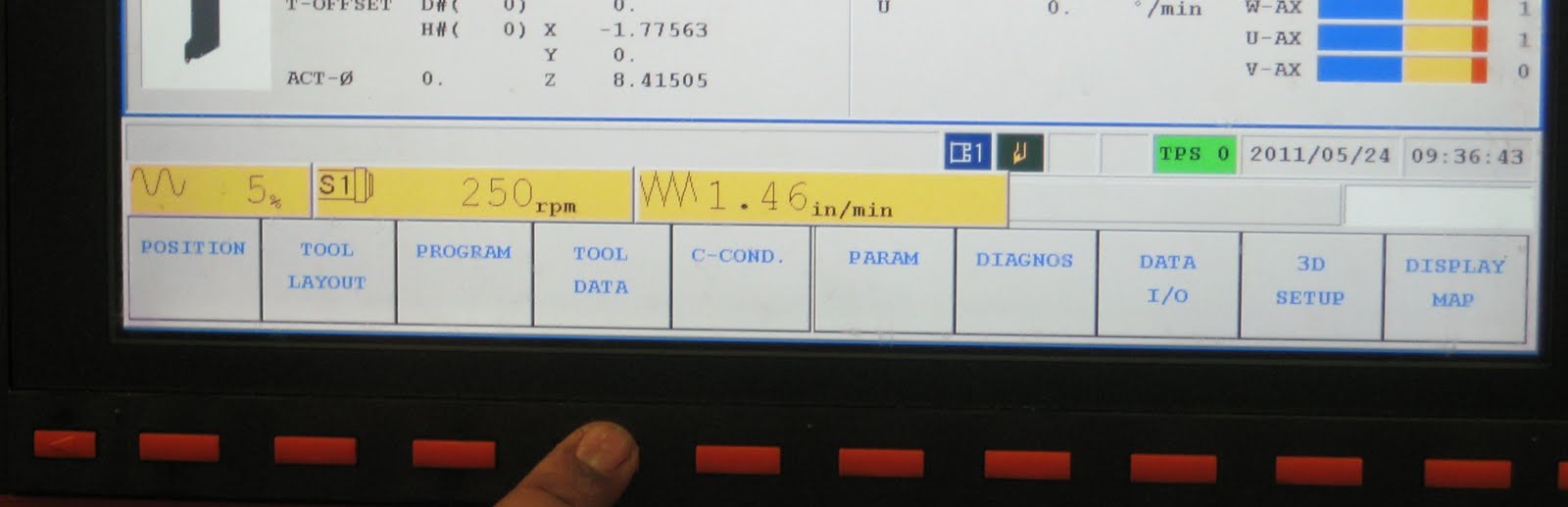
Tool offset is used to compensate for the difference when the tool actually used differs from the imagined tool used in programming (usually, standard tool).In this unit, there is no G code to specify tool offset. The tool offset is specified by T code.Tool offset type:- Geometry offset method Wear offset method Work of
Machine Zero and Program Zero

During every machining operation, the CNC machine uses a series of numerical instructions sent by the part program to control movements along the axes. These programs require a starting point that accurately lines up the cutting tool and the workpiece.Each CNC machine has a built-in location that is called machine zero. This point typically is located at the farthest positive direction along the X-, Y-, and Z-axes, and it cannot be changed by anyone after it leaves the original manufacturer. A cutting tool or a worktable can be moved to the machine zero position for the loading and
Labels:
Machine Zero
Coordinates for the Turning Center

Milling machines are normally used to machine cubic work pieces. However, manufacturers will use turning centers (shown in Figure 1) to shape the dimensions of cylindrical work pieces.During turning operations, the work piece is held and rotated in a spindle. A non-rotating cutting tool is moved against the rotating part to remove material. Because the Z-axis is always parallel to the spindle of the machine, it no longer describes up and down motion of the cutting tool. Instead, the Z-axis now describes the back and forth motion of the tool along the length of the work piece, parallel to
Labels:
CNC Coordintes
Coordinates for the Horizontal Milling Machine

It is true that the axes of the vertical milling machine perfectly match the right-hand rule. However, not all CNC machines follow the same setup. Horizontal milling machines require a shift in the axes because the spindle of these machines is in a different location.Figure 1 shows the basic setup of a horizontal milling machine. As you can see, the spindle is located on the side. Because the Z-axis must always be parallel to the spindle of the machine, the Z-axis is tilted to the side, as shown in Figure 2. The X-axis still describes motion to the left and right. However, the Y-axi
Labels:
CNC Coordintes
How to select tool data in Mazak Matrix Machine
Mazak Integrex E-650 H
Offset 1. How to select tool data 2. how to enter the tool data 3. How to take tool offset 4. How to take work offset 5.
Labels:
Mazak
Welding And Allied Processes

Introduction:- welding is one of the material addition operations where components made by various processes are permanently joined together to obtain the desired configuration .other techniques of joined the components are brazing, soldering, mechanical joining ( riveting ,bolting and keying ) and adhesive bonding. Here we shall consider only welding and some of the allied processes like brazing and soldering .
Labels:
Welding
Coordinates for the Vertical Milling Machine

The most recognizable coordinates can be found on the vertical milling machine. Imagine that you are standing in front of the machine and facing it. The coordinates of this machine follow the right-hand rule shown in Figure 1. As you can see in Figure 2, the X-axis describes left and right motion of the cutting tool, the Y-axis describes back and forth motion of the tool, and the Z-axis describes up and down motion.Depending on the machine, either the cutting tool or the worktable will move during machining operations. The positive and negative directions on each axis always de
Labels:
CNC Coordintes
Standard Axes Locations

The following are general guidelines that determine the location of coordinate axes on any given CNC machine:The Z-axis is always parallel to the spindle of the machine.The X- and Y-axes are always perpendicular to the spindle of the machine.The X-axis normally describes the longer direction of travel on the machine, and the Y-axis describes the shorter direction of travel.Keep in mind that the spindle is different for the machining and turning center. On the machining center, the spindle is the device that holds the rotating cutting tool, as shown in Figure 1. On the turning center
Labels:
CNC Coordintes
Coordinate Standards for Machines

Without a doubt, the two most common CNC machines are the machining center and the turning center. A machining center is used to machine flat or angled surfaces, and a turning center is used to machine cylindrical parts. Figures 1 and 2 illustrate both of these machines.CNC machines rely on the coordinate system to machine incredibly accurate dimensions. This requires a mapping of the coordinate system onto the dimensions of the machine. Imagine applying the right hand rule to a machine. Every CNC machine is programmed to recognize where the X-, Y-, and Z-axes are located on th
Labels:
CNC Coordintes
Coordinate Standards for Machines
A turning center is used to machine cylindrical partsA machining center is used to machine flat or angled surfacesWithout a doubt, the two most common CNC machines are the machining center and the turning center. A machining center is used to machine flat or angled surfaces, and a turning center is used to machine cylindrical parts. Figures 1 and 2 illustrate both of these machines.CNC machines rely on the coordinate system to machine incredibly accurate dimensions. This requires a mapping of the coordinate system onto the dimensions of the machine. Imagine applying the right h
Labels:
CNC Coordintes
Rotational Axes

In addition to the movements on the linear X-, Y-, and Z-axes, tools and workpieces can also move along rotational axes. These rotational axes describe how a part tilts or rotates around a line defined by at least two points. The three rotational axes are the A-axis, B-axis, and C-axis, as shown in Figure 1. Each rotational axis corresponds to one of the linear axes. The A-axis rotates around the X-axis, the B-axis rotates around the Y-axis, and the C-axis rotates around the Z-axis.Rotational movement can describe a workpiece that is turned to expose different areas of its
Labels:
CNC Coordintes
Absolute Coordinates

Though incremental coordinates are used in certain operations, absolute coordinates dictate the movements of both tool and workpiece for most CNC machines.With absolute coordinates, the origin is always in a fixed position. Each new location is calculated from this fixed origin instead of the previous location. Even if there is an error while reaching the current location, that error is corrected once the tool or workpiece moves to the next location. Figures 1 and 2 compare two blueprints that use incremental and absolute calculations.To return to the driving example, absolute coord
Labels:
CNC Coordintes
Incremental Coordinates

As a CNC machine works on a part, the machine guides either the cutting tool or the workpiece from one location to the next. Depending on the operation, a CNC machine will use either incremental coordinates or absolute coordinates to determine this movement.FIgure 1 shows a blueprint with dimensions that reflect incremental coordinates. With incremental coordinates, a new location is calculated from the current position. Once the tool reaches the new location, it becomes the base for the next position. In other words, the current position always acts as the origin for the
Labels:
CNC Coordintes
Coordinates in Blueprints

Every part that is made in the shop is originally designed on a computer or a blueprint drawing. In order to lay out the dimensions of a workpiece, a designer uses a coordinate system to describe the measurements of each dimension. Figure shows a blueprint drawing that contains these measurements.Bot
Labels:
CNC Coordintes
Positive and Negative Directions

Figure 1. Each axis has a positive and negative direction.Figure 2. The positive direction of the Y-axis points away, and the positive direction of the Z-axis points upward. Each axis line contains a range of numbers. The origin, or the center of the axis line, is always zero. Numbers are then counted as they move away from the center on each side of the axis. One direction is positive (+), and the other is negative (-).Measurements taken to the right si
Labels:
CNC Coordintes